
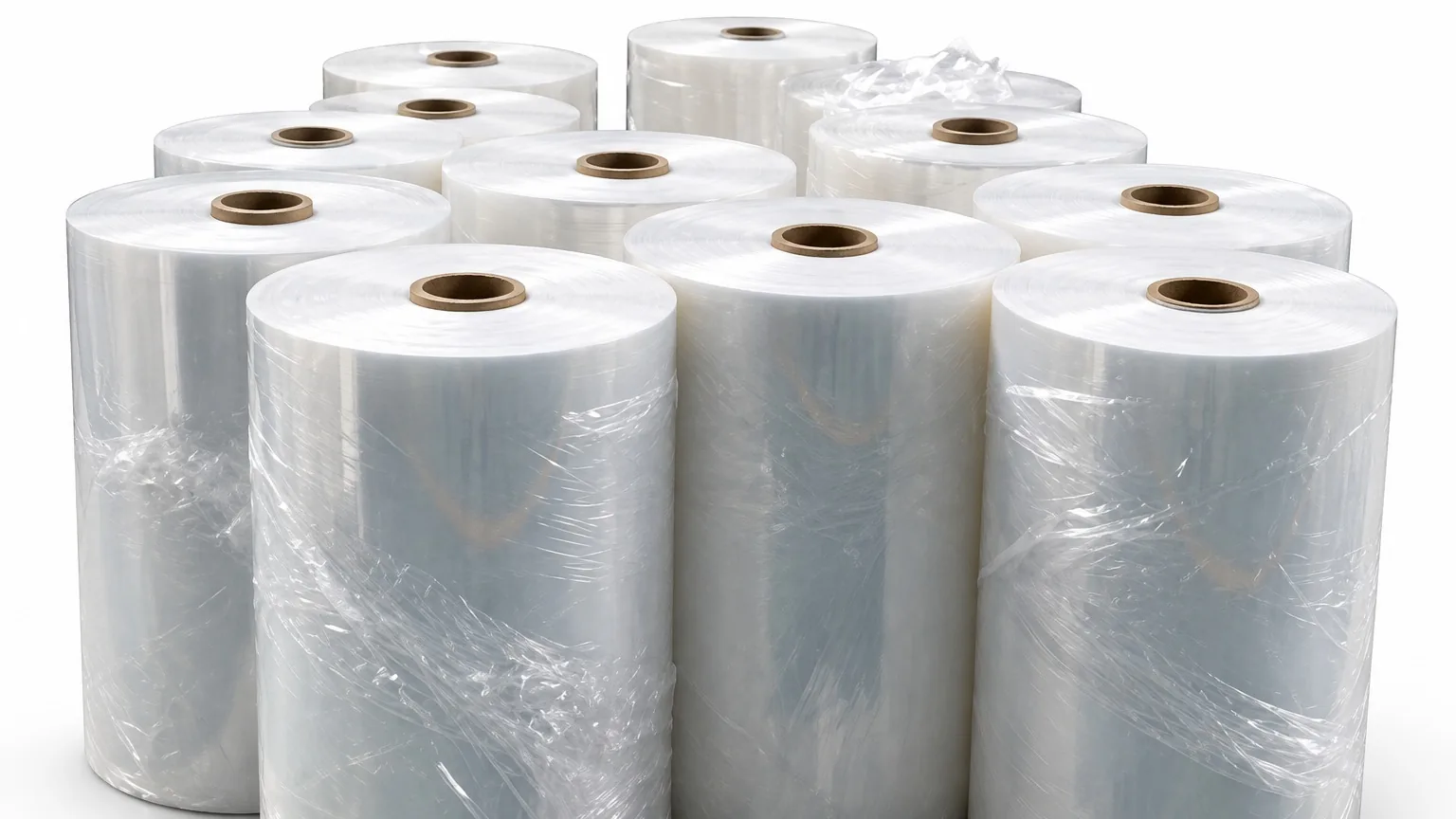
Protective film can be cut to the programmed length and still arrive at the next workstation in poor condition. A sheet may contain wrinkles, pressure marks, trapped dust or a lifted edge. Lightweight pieces can also cling together, curl or slide out of order after the blade. For a buyer, the important question is not simply whether a machine cuts film, but whether it delivers usable sheets without creating new surface or handling defects.
This guide turns that question into a practical roll-to-sheet trial. It follows the film from the incoming roll through pre-feeding, guidance, cutting and conveyor discharge, then separates documented machine configuration from requirements that need project review.
1. Define the Accepted Protective Film Sheet
Begin with the finished part. State target length and width, measurement datum, permitted variation, squareness method and acceptable cut-edge condition. Identify the protected surface and whether the film has an adhesive layer, liner, coating, printing or masking layer. Specify whether wrinkles, roller marks, dust, adhesive transfer or lifted corners are rejection conditions.
| Buyer concern | Evidence to record | Process area to observe |
|---|---|---|
| Wrinkles or trapped folds | Both faces under consistent lighting | Roll release, pre-feeding, guidance and roller pressure |
| Length variation | Consecutive measurements in production order | Roll tension, feed contact, settings and measurement |
| Surface contamination | Accepted and rejected reference samples | Roller, blade area, conveyor and operator handling |
| Clinging or poor stacking | Accepted sheets, rejects and handling time | Discharge, conveyor speed and collection method |
Keep the display setting separate from the finished-sheet tolerance. Define how the sheet will be supported and measured, especially when a soft or curled part can change dimension under hand tension.
2. Record the Real Roll Construction
“Protective film” covers many constructions. Record the supplier’s material identification, total thickness, web width, critical face and winding orientation. Add roll outside diameter, core inside diameter, roll weight, edge condition and splice locations. Note any adhesive, release liner, coating or printed repeat.
Use representative production material rather than a convenient substitute. Surface tack, stiffness, friction and static behaviour can alter roll release, feed grip and sheet separation. Mark the inside and outside faces and explain what the sheet protects downstream.
3. Follow the Complete Material Path
Watch the roll stand, release point, spring-loaded pre-feeder, guides, feed rollers, cross-cutting section, conveyor and collection area. The roll should release without sudden drag. The web should remain laterally aligned without a guide scraping its edge. Roller pressure should maintain feed contact without creating an unacceptable impression or transferring contamination.
After cutting, inspect whether the conveyor supports the full sheet and whether pieces remain in order. A sheet that meets length requirements but folds, overlaps or gathers dust during discharge is not a complete success. Include collection labour and rejected pieces when comparing usable output.
4. Run a Traceable Cutting Trial
Use one documented setup and preserve sample sequence. A useful test includes:
- Inspect the incoming roll for telescoping, damaged edges, contamination, loose winding and splices.
- Record roll orientation, guide positions, roller pressure, length, speed, quantity, batch and pause settings.
- Collect consecutive sheets near the beginning, middle and later portion of the trial roll.
- Measure length and squareness with the same tools, datum and support method.
- Inspect the critical face, back face, cut edge and corners under controlled lighting.
- Repeat after a normal stop and restart, and after a roll or size change where applicable.
Report individual measurements instead of only an average. A consistent offset, gradual drift and occasional outlier indicate different questions. Record the first sample affected whenever pressure, speed, guidance or discharge conditions change.
5. Match the Test to HESPER’s Documented Configuration
The HESPER Film, Paper and Fabric Cutting Machine with Spring-Loaded Pre-Feeder and Conveyor lists protective film among its materials. Its process combines pre-feeding, cut-to-length cross-cutting and conveyor discharge. The Chinese/English LCD and keypad provide settings for length, speed, total quantity, batch quantity and pause time.
The documented equipment includes Panasonic photoelectric sensing, polyurethane feed rollers with pressure adjustment at both ends, a separate bearing-supported roll stand, an SKD11 blade, a closed-loop cutting motor and cooling fans. Models CXY-300T, CXY-400T, CXY-500T and CXY-600T correspond to listed working widths of 300, 400, 500 and 600 mm.
The published data lists 0.01 mm feeding accuracy, 700 mm/s feed speed and 1.2 kW power. Feeding accuracy is not the same as guaranteed finished-sheet tolerance, and feed speed is not accepted production output. Both must be evaluated with the actual protective film, roll condition, cut length and collection requirement. Use the HESPER unwind-roll specification guide to prepare the roll data before testing.
6. Separate Standard Processing From Project Needs
The documented machine performs roll feeding, cross-cutting and conveyor discharge. If the job also needs longitudinal slitting, printed-mark registration, a particular anti-static arrangement, automated stacking, liner separation or connection to another line, describe each result separately. Do not assume these functions are included.
Photoelectric sensing is documented, but sensing behaviour can depend on film transparency, surface reflection and the mark or target being detected. Provide a material sample and representative printed mark if registration matters. Ask HESPER to confirm the proposed sensing and collection method through a trial.
Frequently Asked Questions
Does 0.01 mm feeding accuracy guarantee the same finished-sheet tolerance?
No. Finished results also depend on roll release, material behaviour, feed contact, cutting and measurement. Approve consecutive measured samples against your own tolerance.
How should protective-film wrinkles be inspected?
Define the lighting, support surface and accepted reference. Inspect pieces from different trial stages, including after stops and setting changes.
Can transparent film always be detected by a photoelectric sensor?
Do not assume universal detection. Transparency, reflection, background and the required target can affect sensing. Test the real material and mark condition.
What should the RFQ include?
Include film construction, thickness, roll width, diameter, core and weight; finished-sheet dimensions and tolerance; surface criteria; batch size; collection requirement; and sample availability.
Send HESPER a Measurable Film Requirement
Use the HESPER project enquiry to send roll data, a finished-sheet drawing, defect photographs and your inspection method. HESPER can review the material path, working width, sensor condition and trial criteria before the configuration is confirmed.