
Short answer
6 bar alone does not tell you whether a cutter can cut your material. At that pressure, cylinder bore determines the theoretical force, but the cutting stroke, blade mechanism and material determine whether a particular setup is suitable.
Start by calculating the theoretical cylinder force, then check the blade mechanism and verify the candidate setup with your actual material. If more force is needed, a larger bore or a different mechanism may be options, subject to air-supply capacity and the rated limits of the complete assembly. The table and checks below help you prepare for that discussion.
A real enquiry about a cutting head
A customer assembling artificial flowers into pots asked about a standalone pneumatic cutting head to fit beneath an existing workstation table. They described these requirements:
- Stems mainly made of plastic, with a maximum diameter of 20 mm.
- Approximately 4–6 steel wires per stem, each approximately 0.2–0.5 mm in diameter.
- Available compressed air of 6 bar.
- Manual feeding, foot-pedal operation and a target of 5–10 cuts per minute.
They requested the cutting force at approximately 6 bar, along with a recommended configuration and other technical details. These are customer requirements, not verified cutting results. The pressure figure alone does not establish the required bore or confirm that a particular head can cut those stems.
How to calculate pneumatic cylinder force
Start with pressure multiplied by effective piston area. The bore is the cylinder’s internal diameter. For a conventional double-acting, single-rod cylinder on its extension stroke:
Here, p is gauge pressure at the cylinder—the pressure relative to atmosphere shown by a suitable pressure gauge—and D is bore diameter. The calculation assumes the opposite chamber is exhausted to atmosphere and ignores friction, pressure remaining in the exhausting chamber that opposes motion, and other losses. It is a cylinder-force estimate, not a measured force at the blade. Festo’s cylinder-sizing reference distinguishes piston area, rod area and friction.
For example, a 50 mm bore at 6 bar gives approximately 1,178 N, or 120.1 kgf. Kilogram-force is a force unit, not a statement of lifting capacity. At the same pressure, doubling the bore gives four times the theoretical force.
For the retraction stroke, subtract the rod’s area:
Here, d is rod diameter. Use whichever stroke actually performs the cut. A head mounted under a table could have different arrangements; its location alone does not tell you which stroke cuts. Spring-return or other cylinder designs require their own manufacturer data.
Pneumatic cylinder force calculator: 6 bar table
The values below are theoretical extension forces for the assumptions above. They are not HESPER machine ratings or guaranteed cutting capacities.
| Bore (mm) | Theoretical extension force (N) | Equivalent force (kgf) |
|---|---|---|
| 32 | 483 | 49.2 |
| 40 | 754 | 76.9 |
| 50 | 1,178 | 120.1 |
| 63 | 1,870 | 190.7 |
| 80 | 3,016 | 307.5 |
| 100 | 4,712 | 480.5 |
Calculated from F = pA with 6 bar = 0.6 N/mm² and 1 kgf = 9.80665 N. Values are rounded. At 5 bar, multiply the force by 5/6; at 7 bar, by 7/6. A calculation at a higher pressure is not permission to exceed any component’s rated pressure.
Why theoretical force is not the final selection
The cylinder has to operate with friction, changing chamber pressures and the moving mechanism. A linkage can also change the relationship between cylinder force and blade force. Blade condition and material variation affect the load that must be cut.
Do not apply a universal “use 70%” rule. SMC’s selection guide assigns different load factors to different operating conditions. A selection load factor is not a measured efficiency for every cutter. The appropriate allowance must come from the cylinder supplier’s guidance and the actual mechanism and duty.
For a simple pressure comparison, a 63 mm bore gives about 1,870 N theoretical extension force at 6 bar, but about 1,559 N at 5 bar. Neither number establishes that a 63 mm cylinder will cut the customer’s stems.
Steel wire inside needs a separate check
The stem combines mainly plastic material with internal steel wires, so both need to be considered. Its outside diameter does not describe the full cutting task. Identify the wire grade and hardness, number and diameter of wires, surrounding material and how the stem is supported.
Ask the supplier to confirm the blade specification and suitability for that combination. Discuss whether a representative sample test can be arranged, including cut quality and blade condition over repeated cuts. Ask about replacement availability and price; blade life cannot be established from a photograph.
What size pneumatic cylinder do I need? Four checks
1. Establish the material and required load
Provide representative samples or a clear material specification. Agree how a proposed cutter will be evaluated. A successful cut under recorded conditions is useful evidence; measuring the cutting force requires a force gauge or load cell suitable for the test. Do not describe a value calculated from air pressure and bore as a measured blade force.
2. Check the complete mechanism
Confirm bore, rod diameter, cylinder type, stroke and which direction cuts. Include any linkage ratio, guides and the manufacturer’s applicable load allowance. Select a candidate for verification rather than treating the first suitable table row as a final machine recommendation.
3. Check pressure and air delivery during operation
A compressor or upstream gauge reading does not necessarily equal cylinder pressure during a cut. Check pressure close to the cylinder under the intended operating conditions, including other equipment running. Have the supplier assess valves, tubing and air delivery for the required stroke speed.
4. Verify the whole cycle
Five to ten cuts per minute means an average cycle of 6–12 seconds. That includes feeding, cutting and return; it does not specify the instantaneous blade speed. Verify the full cycle, cut quality and repeatability. For manual feeding, confirm suitable guarding and controls as part of workstation integration.
Blade geometry: check the installed arrangement
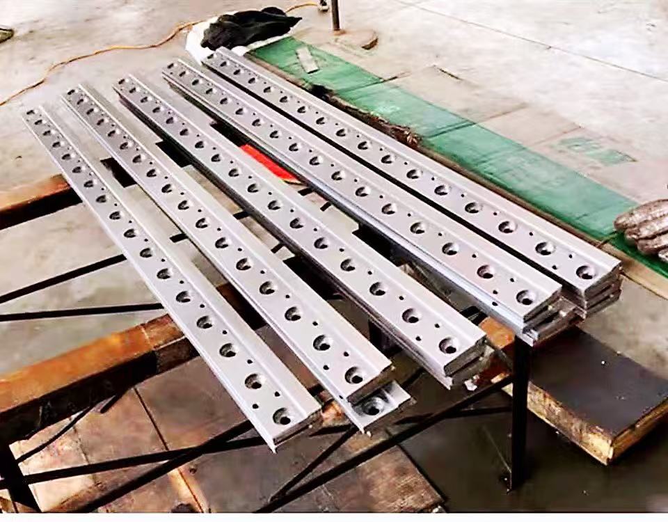
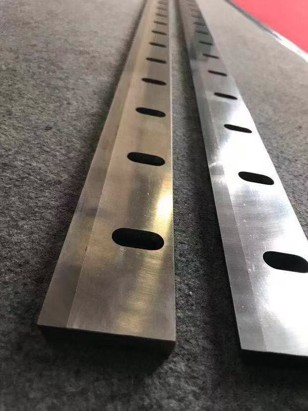
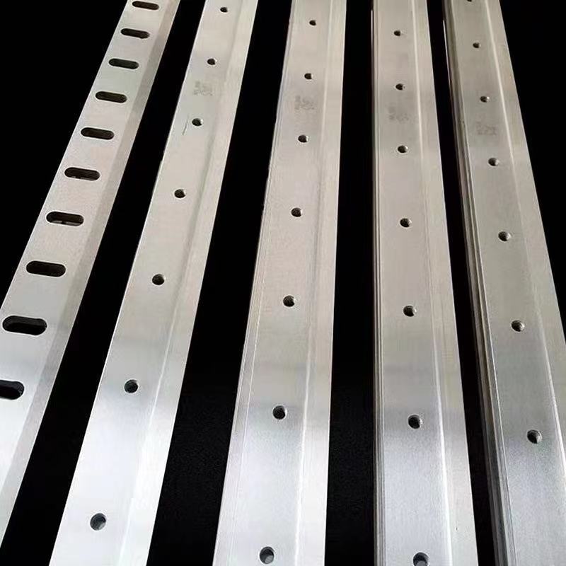
For a pneumatic guillotine cutter, ask how the blade engages the material, how it is guided and what clearance it needs against the counter-blade—the opposing blade that works with it to make the cut. The bevel ground on a blade and the angle at which the blade is installed are different things. A loose-blade photograph cannot establish the installed cutting geometry or its force requirement.
FAQ
Is 6 bar enough for a pneumatic cutter?
Pressure alone cannot answer this. Check the cylinder bore, cutting stroke, blade mechanism, pressure during cutting and the force required by the actual material. Confirm the proposed configuration with a representative sample test.
How do I calculate pneumatic cylinder force?
For the ideal extension stroke of a conventional double-acting, single-rod cylinder: F (N) = p (bar) × 0.07854 × D² (mm²). This assumes gauge pressure at the cylinder and the opposite chamber exhausted to atmosphere; friction and other losses are excluded.
Can I use this pneumatic cylinder force calculator table at other pressures?
Yes, for the same theoretical extension calculation: multiply a 6 bar value by your pressure divided by 6. Use pressure at the cylinder under the relevant operating conditions and stay within the rated limits of the complete assembly.
Can a pneumatic cutter cut steel wire?
When evaluating a pneumatic wire cutter, confirm that both the cutting mechanism and blade are suitable for the specific wire. Wire diameter, number of wires, grade, hardness, blade geometry and clearance all need checking. These photos and force calculations do not establish a steel-wire cutting capacity for a HESPER model.
Why is retraction force lower than extension force?
For a conventional single-rod cylinder at the same pressure, the rod reduces the effective area on the rod side. Use the force for whichever stroke performs the cut. Retraction does not necessarily mean upward movement, and extension does not necessarily mean downward movement.
Can I buy only the cutting head and build it into my workstation?
Ask us whether a standalone cutting head is available for your application and what it would include. Before integration, confirm mounting, travel, control interfaces and guarding with the supplier and the person responsible for the workstation.
Discuss your cutting requirement
Send the material, maximum diameter or thickness, internal reinforcement, a cross-section photo, available air pressure, required cuts per minute and installation space. Contact HESPER with these details to discuss possible configurations, the cutting capability that needs verifying, and whether a sample test can be arranged.
Send an enquiry or email sales@hespermachine.com.
Technical references
- SMC — Air Cylinders Model Selection: selection by operating conditions and cylinder direction.
- Festo — Cylinder Sizing by Piston Force, page 23: effective piston area and cylinder output.
These references explain general cylinder selection. They do not certify a HESPER cutting head or the application described above.